![]()
e-Mail: contact@zena.net
| Go to: |
|
|||
|
|
|
|||
|
|
|
Detailed ZENA® Welder Installation Notes
|
e-Mail: contact@zena.net |
Detailed ZENA® Welder Installation Notes |
||||||||||||||||
PAGE UNDER CONSTRUCTION
Overview
A
ZENA portable welding system can be attached to any suitable engine, or installed
into virtually any vehicle (tractors, ATV's, trucks, emergency vehicles, forklifts,
construction equipment, water craft, lawn tractors, etc.) capable of producing sufficient
power for the chosen generator. Once installed in a vehicle, the entire vehicle is
transformed into a self-contained portable welding station -- with performance and
operating features that equal, or exceed, heavy, bulky, and very expensive transportable
engine-driven industrial welders.
When properly installed, the ZENA power generating equipment is completely isolated
from the vehicle or drive engine's electrical system, reducing the chance of damage
to the electrical system when welding, and allowing standard polarity (negative electrode)
welding -- even on the vehicle in which the welder is installed.
The information presented here is meant to be general in nature -- composed for individuals with the technical competency necessary for the installation and/or retrofit of electrical, mechanical, and/or electromechanical equipment to an engine, or into a motorized vehicle.
NOTE:
While this section is more detailed than our installation overview page, it is not to be considered a replacement for the Operators Manual which has more information than is presented here.
Particularly
in the case of post 1985 automotive installations, where sensitive microcomputer
devices are in use, we recommend that installation be performed by individuals who
are familiar with a given vehicle's electrical systems. Some of these vehicles have
electrical systems which are so fragile that they can be seriously damaged by maintenance
activities as simple as routine battery replacement.
Actual installation of the ZENA system is usually quite simple and straightforward
in its concept, but there is a high degree of variation from one vehicle to another.
Further, in any particular vehicle, there can be many correct installations. Therefore,
we often simply advise what not to do, rather than trying to provide specific instructions
which would, in all likelihood, only apply to a single situation.
Mechanical
Installation
Mechanical installation is typically simple and straightforward.
Keep these points in mind when planning your installation:
For
example, engine welding speed for a powerful tractor (40-100 HP) might be determined
to be approximately 2,500 RPM. However, in this case, by selecting and installing
an inexpensive larger diameter secondary crank pulley in front of the engines stock
crank pulley, engine welding speed could be reduced to approximately 1,600 RPM.
OR,
with this same tractor, the use of the Add-A-Pulley, and a smaller than stock drive
pulley on the tractor's existing alternator can reduce engine speed even more --
in this example, welding speed could be at as little as 1,250 rpm.
Idler
Pulley
Spring
Loaded NOTE:
When
making your calculations, remember that if you are driving your Power Generator from
an existing alternator using a ZENA Add-A-Pulley alternator power take off pulley,
in most cases, there will be a built-in 10-40% reduction of needed engine speed for
welding (reduction determined by ratio of existing alternator pulled diameter to
Add-A-Pulley pulley diameter). This means that if 2,500 RPM would be the proper engine
speed (per the engine speed for welding determination charts), you would only need
a speed of 2,000 to 1,500 RPM when using the Add-A-Pulley accessory.


Tensioner Part#
AI RT1001
When using smaller than normal pulleys, the use of idler pulleys and spring loaded
tensioners may be necessary to insure that belts do not slip or experience accelerated
wear.
d) Since the method of drive chosen, may effect the positioning of components and the design of bracketing for a particular installation, it is important to make these decisions BEFORE beginning the installation. Your dealer, or our technical support personnel, will be happy to assist you in developing an installation plan for your application.
CAUTION / NOTE:
DO NOT make the mistake modifying drive pulley ratios to the point that an engine welding speed which is less than approximately 50% of maximum engine rpm is achieved. Doing this can cause the welding power generator to over-speed when engine speed is increased to maximum during normal vehicle use.
2. Power Generator Positioning / Rotation
a) ZENA's proprietary power generating technology (and a very efficient forced air
cooling system which draws cool air in from the rear and exhausts heated air from
the front) provides such an efficient power generating system that, in free air conditions,
even when welding continuously at full power, ZENA's Power Generator stays remarkably
cool -- usually cool enough so that it can be touched without undue discomfort. However,
real-world conditions are never perfect, so the ZENA system has been designed to
operate reliably in the very high ambient air temperatures that exist under the hood
in motor vehicles.
For maximum performance, trouble-free operation, and a long service life, plan to
mount the Power Generator so that ample cool air is available to supply its forced
air cooling system. For example, avoid mounting positions where air is hot and not
moving and/or where the superheated air from an engine's exhaust system will be
drawn into the rear of the Power Generator. Such a heat source can, by itself, heat
the Generator to temperatures which will damage internal components..
b) In automotive installations, a supply of relatively cool air for the welding system's
Power Generator can be obtained by installing a well positioned, high efficiency,
electric radiator cooling fan and/or large diameter non-collapsible duct hose so
that cool air from outside the engine compartment will be directed to the rear of
the Power Generator, or (in some cases) by simply insuring that the vehicle's engine
compartment hood in its open position when welding.
c) If possible, insure that the chosen mounting point is one which allows the operator
to easily attach welding and control cables to the Power Generator. Where this is
not possible, or where extra convenience is desired, consider the installation of
one of ZENA's external welding cable quick disconnect kits (model BJ150 or BJ200).
d) Drive pulley/belt alignment is critical for vibration free operation and long
belt life. Every effort should be made to insure precise alignment between components.
e) Consider a piggyback installation. This most popular type of installation uses
the existing engine alternator (which is fitted with a double pulley) as the drive
element for the Power Generator (which is mounted in close proximity to the alternator)
-- often using the existing alternator bracketing as part of the new Power Generator
bracketing. The double pulley on the alternator allows a short (typically 21-26)
drive belt to be attached between the Power Generator and the alternator.
To make this sort of installation possible for engines which use a serpentine drive
belt system, and to make installations onto V-belt equipped engines even easier,
we have developed the Add-a-Pulley retrofittable secondary alternator pulley . The
Add-a-Pulley fits almost all existing automotive alternator designs, and come with
all necessary parts to retrofit an existing alternator or with a secondary drive
pulley that can be used to drive the Power Generator. See Appendix E for more information.
f) The direction of rotation AND the physical (front to rear) positioning of the
Power Generator, relative to the engine, are not critical. The Power Generator will
operate properly when rotating in either its normal clockwise direction or in a counterclockwise
direction and/or when mounted with its front (the end with the pulley and cooling
fan) pointing towards the rear or the front of the engine.
CAUTION / NOTE:
The shaft end nut which secures the cooling fan and the drive pulley to the front
of the Power Generator is self tightening/locking in normal CLOCKWISE rotation.
If the Power Generator is used in a mode where COUNTERCLOCKWISE rotation occurs,
the shaft end nut MUST be secured to the threaded portion of the Power Generator
drive shaft with an appropriate high strength, high temperature chemical threadlocker.
(LOCTITE® type 272 high strength, high temperature threadlocker recommended.)
Also, the points of contact between the fan and the drive pulley and the drive pulley
and the nut should be strengthened/reinforced with an appropriate stud locking compound.
(LOCTITE® type 648 high strength, high temperature retaining compound recommended.)
These recommended locking chemicals are designed for permanent assembly. Disassembly
can be difficult and requires the use of tools, and the application of heat to soften
the locking material for removal.
DO NOT APPLY THREADLOCKERS UNTIL AFTER YOU ARE COMPLETELY SATISFIED WITH YOUR FULLY
COMPLETED WELDER INSTALLATION (including any clocking operation -- see item #6 which
follows).
3. Bracketing
There are a number of vehicles in which a bolt-in installation, using existing brackets,
can be accomplished. More typically, however, new brackets will be required for mounting
the belt-driven Power Generator -- positioning the Power Generator as noted previously,
and so that a clear path is available for the attachment of the existing drive belt
(or a new drive belt) from the Power Generator to
l the engine's crankshaft pulley, or
l to the engine's existing alternator (using a secondary pulley),
l to the engine's flywheel, or
l to some other appropriate drive/power takeoff point.
Remember that your welding Power Generator is air cooled, and that it should be mounted
in a position which is as far as possible from the engine exhaust system or other
areas in which high ambient air temperatures may be found. Where this is not possible,
metal heat shields should be used to protect the unit from excessive heat and/or
ducting can be provided to route cool air to the cooling air intake vents at the
rear of the Power Generator.
Initial consideration should be given to using an existing (factory installed), but
unused, mounting bracket and/or bracket mounting fittings. For example, many vehicle
engines are designed to accommodate a second alternator, a belt-driven air compressor,
or a high capacity hydraulic pump. If these devices are not installed, the ZENA welding
Power Generator can often be mounted to these existing fittings using either simple
custom-fabricated brackets and/or parts of accessory installation kits which are
often available from the vehicle's manufacturer. For example, many tractors are designed
to have optional air conditioning systems installed. It is often possible to use
the brackets and idlers which come with these kits for a Power Generator installation
that will require little or no additional modification.
If you are not able to use existing mounting brackets, custom brackets must be fabricated.
To assist you, prefabricated universal mounting brackets such as the model A300 and
other bracket fabrication components which can be used to construct your custom brackets,
are available from ZENA, or through other commercial sources . Often an installation
may require both prefabricated mounting brackets and some other simple parts and/or
brackets which must fabricated by the installer. See Appendix A and Appendix B for
examples.
Make your bracket(s) strong-- when installed, your Power Generator must be mounted
in a way which leaves it just as firmly placed as your existing alternator, air conditioning
compressor, or power steering pump.
Typically we recommend that bracket parts be constructed from steel stock which is
at least 5/16 inch thick (3/8 inch or even 1/2 is even better). All bar stock used
should be at least 1 in width (1-1/4 is even better). When using angle stock, we
recommend 2 x 5/16 angle for most applications. When in doubt, always choose materials
which will result in a stiffer/stronger support system, rather than materials which
will yield a less stiff/weaker support.
Brackets may be welded together to insure maximum strength (or may be assembled quite
successfully with nuts and bolts). However, we strongly recommend that the Power
Generator's mounting bracket(s) be first mounted with removable fasteners and that
bolt holes be oversize or slotted. Use at least two 5/16 bolts to attach the Power
Generator bracket to other bracketing components. Using bolts for Power Generator
attachment allows you to make adjustments, before any welding), necessary to insure
perfect alignment of the Power Generator to the power take off point on the engine.
Most automotive engines are mounted to the vehicle frame using some sort of flexible
shock mount. When attaching a Power Generator to this type of engine, the Power Generator's
mounting bracketing MUST be attached exclusively to the engine and/or to other components
which are attached exclusively to the engine. Failure to do this can result in severe,
and potentially damaging, vibration and very short drive belt life.
When mounting a Power Generator to tractors and other vehicles which directly, and
firmly, mount the engine to the frame of the vehicle, the bracketing for the Power
Generator may be attached directly to any part of the vehicle which is sturdy enough
to provide proper support. Do not, however, attach any portion of the Power Generator
bracketing to any mounting point or frame member which is also used to attach a front
end loader or other similar equipment to the vehicle. This sort of equipment is subject
to slight, but continuous, movement on the vehicle. This slight movement can easily
cause belt alignment to vary to an unacceptable degree when mounting points are shared.
4. Bracket Fabrication Tips
Save money, save time, and minimize wear and tear to your tools:
a) Use heavy CARDBOARD to work out bracket designs. And, by taking cardboard forms
with you to buy steel, you may get your vendor to do the rough cutting.
(Cardboard pieces can also insure proper welder to hood clearance. Place a couple
of thickness of cardboard where clearance are tight, and close the hood, a bit at
a time, observing the cardboard for indentations which indicate too little clearance.)
b) Installers report the most used sizes of steel used in fabricating brackets are:
2x5/16 angle, 3x5/16 angle, 1-1/4x5/16 bar, 1x5/16 bar, 1-1/4x3/8 bar,
and 1x3/8 bar.
c) If you don't have a supply of steel on hand, consider purchasing what you need
from a local machine shop, welding shop, trailer fabricator, or other business involved
in steel fabrication work. Their prices will be much less than hardware stores and
(since you'll be buying small pieces of their scrap stock) you won't have to buy
more metal than you need (as is be the case with bulk steel suppliers).
Check to insure that the pulleys are in parallel alignment with a straightedge, making
sure that the straightedge contacts both the Power Generator pulley and the pulley
to which it is being aligned at two points on the surface of each. Using the same
straightedge, make sure that the V's of both pulleys are in perfect alignment as
well.
Make sure that V-belts run straight and true. Belts which are mis-aligned will also
cause excessive frictional heating of the V-belt and excessive mechanical wear which
will result in premature belt failure. It is very important that the path of the
drive belt be straight. Brackets should always be made (and installed) so that initial
adjustment is possible. Often, this may just mean using slightly oversize mounting
holes or simple slots. (After initial adjustment, tack welding may be done to prevent
unwanted motion.)
Finally, insure that all pulleys in drive path have appropriate drive belt wrap/surface
area contract (at least 40% of circumference for larger pulleys -- 55-70% for smaller).
5. Drive Belts
After the brackets are installed and the Power Generating unit has been properly
and securely mounted, a correctly sized drive belt (.3750 inch for the Series 150
/ .5 inch belt for Series 200 welders) is attached to the chosen drive source , and
properly tensioned.
NOTE:
In some cases, it may be desirable to fit dual drive pulleys and use dual drive belts
-- less tension is required, adjustment intervals may be longer, and belt life may
be extended. A wide range of special double V pulleys are available from our parts
department -- call to discuss your specific needs.
DO NOT USE lawn mower/agricultural implement type V-belts (fabric covered) to drive
the ZENA welding Power Generator. They slip during operation and produce a large
amount heat when used with small pulleys operating at high speeds. Use ONLY high-quality,
soft rubber (rather than hard, inflexible rubber premium/HD), automotive type V-belts.
We have found the bottom-cog type belt (available from most after-market auto parts
suppliers in the USA) to be most effective.
Don't over or under tighten drive belts. This will cause excessive frictional heating
of the V-belt and drive pulleys, extra strain on bearings and internal electrical
components, and will result in premature belt failure. A slipping belt is sometimes
hard to detect -- a hot pulley is a sure sign of slipping. Tighten belts just enough
to prevent any slipping or squealing when operating your welder at full power.
ALWAYS static test belt tension by using a properly sized wrench on the power generator's
pulley bolt to try to rotate the power generator in a CW direction. It should be
quite difficult to turn using moderate hand pressure. Often a small engine will turn
over before any belt slip will be noted. If any slippage is noted, the point of
failure will be easy to determine.
ALWAYS recheck belt tightness after the first couple of hours of welding. We DO NOT
recommend the use of belt dressings for most applications -- particularly those where
the system is operated in dirty or dusty conditions.
NOTE -- V-belt wrap around pulleys is more important than belt tension:
For example, some trucks, and other vehicles with serpentine belt accessory drive
systems may have alternators which have BOTH a very small (2.5 diameter) alternator
drive pulley fitted AND provide only very minimal belt wrap around this drive pulley
(30% of diameter or less).
In this case, if using as Add-A-Pulley power take off accessory, serpentine belt
slipping at the alternator pulley may occur when welding at higher power settings.
This sort of slipping CANNOT be prevented by simply tightening or replacing worn
OEM serpentine belts.
To obtain proper drive for your welder, it may be necessary to install an idler
pulley to redirect the V and/or the serpentine belt path to insure a good wrap
around ALL small pulleys (55-70%). (If this is necessary, it may also be necessary
to obtain different length serpentine or V belts).
6. Clocking Power Generator and/or Repositioning Control Module
In some cases, installation of the Power Generator will leave it oriented so that
the operator cannot easily attach the welding cables, or you may find that the Control
Module will physically interfere with some existing component unless it is relocated.
Other than to avoid heat, Control Module mounting is not critical. It may be moved
to any of the four bolts which hold the front and rear case parts of the Power Generator
together or to any other convenient point on the vehicle near the Power Generator.
Changing the orientation of the welding cable terminals to the Power Generator's
mounting points is called clocking. This procedure allows the installer to reposition
the external welding lead terminals by rotating the front portion of the Power Generator
90°, 180°, or 270° from its stock position relative to the rear case
portion. Clocking the Power Generator is a simple process:
a) Using an impact wrench, remove the large nut which holds the V-belt pulley and
cooling fan to the front of the Power Generator.
b) Taking care NOT to separate the front and rear case parts, remove the four bolts
which hold the front and rear case parts together.
c) Place the Power Generator on a workbench with the shaft pointing up, and with
the welding lead terminals down taking care to protect the terminals from damage.
d) While maintaining pressure on the shaft to keep it from moving away from the rear
case, lift the front case up slightly and rotate it so that proper orientation is
achieved.
e) Reinstall and tighten the bolts which hold the case parts together, attaching
the Control Module to the Power Generator case with one of the screws (if so desired).
f) Complete by reinstalling fan and pulley. Tighten the nut with an impact wrench.
7. Final Check / Other Considerations
a) Check that bracketing is strong, that all bolts (including drive pulley nut --
use impact wrench) are tight, and that cooling air is available at rear of generator.
Check all electrical connections. Insure that wires are secure and routed properly.
b) In some cases, simple sheet metal covers may be used to further dress-up the installation,
to shield hands and arms from moving components, etc.
c) Also, we recommend that some means of carrying welding rods and welding cables,
helmet, and other tools be provided. A medium sized plastic utility chest is ideal.
7. Multi-Generator Welding Systems --- 300A and larger
l Generators which have outputs combined for higher amperages must be driven at the
same speed. Electrical connections are standard with each generator. The only special
wiring requirement is to interconnect all generators using the yellow control lead,
built into master and slave control modules, with the yellow hookup wire, and connectors,
supplied with your multiunit welding system. Power output leads are all run to a
central connection point to which welding cables are then attached.
l Multi generator systems designed, for use by multiple operators, which do not feature
combined outputs can have generators turning at different speeds -- though, the slowest
unit in the group must be turning at a proper welding speed. No special interconnection
is required.
C. Determining Proper Operating Speed (Tachometer Available)
The Welding Power Generator has been designed to provide optimum performance when
rotating at approximately 6,500 RPM. Operating faster than this has no ill effect
whatsoever. Operating slower will still allow you to weld, but will produce less
welding power than may be needed for larger size rods/electrodes. (Faster is better
than slower.)
Low engine speed is the culprit in 99% of welding power trouble reports.
To determine the proper engine operating speed range for welding for your vehicle:
1) Measure the diameter of your motor's crank pulley and find that diameter on one
of the following four charts (Read chart and column headings carefully to insure
that you are using the correct chart for your intended installation.)
2) Your desired operating speed range is found to the right of your crank pulley
diameter.
3. If using one of our Add-A-Pulley universal alternator power take off units, the
following formula can be used to determine the effect of the AAPK on welding speed:
1 - (alt. drive pulley diameter / Add-A-Pulley diameter ) = % reduction in speed
For example, if you have an existing alternator with a 2.75 pulley, and you are
using an Add-A-Pulley in your installation, the formula
1 - (2.75 / 3.5) = 21%
shows that you can expect a 21% reduction in welding speed when using the Add-A-Pulley.
Therefore, if the Speed Chart, for your particular welder model series, shows a target
speed of 2,000 rpm, using the Add-A-Pulley would reduce this target welding speed
by approximately 420 rpm [ 2,000 * .21 = 420 ]
4. If your target engine speed for welding is not at least 2-1/2 times your engine's
idle speed, sufficient power for welding may not be available. In this case, a LARGER
diameter Power Generator drive pulley (usually 3 to 3. 5 in dia.) must be fitted.
D. Determining Proper Operating Speed (Tachometer NOT Available)
If a tachometer is not available an appropriate welding speed can be determined by
performing a test weld under controlled conditions:
1. Set the Power Control dial on the electrode holder to a position approximately
2/3 to 3/4 of maximum (CW).
2. Set the engine (by ear) to a fast idle (2,000-2,500 rpm).
3. Make a test weld on a clean (not rusty or painted) piece of mild steel 1/4 bar,
plate, or angle stock using a 1/8 type 7018, 6011, or 6014 welding rod.
4. Speed is correct when arc starts easily, and weld penetration of 99-100% can be
accomplished. (Set the speed a little on the high side to compensate for engine loading.)
E. Engine Speed Control
ZENA Automatic Engine Speed Control
(for engines w/vacuum supply)
In many cases, an appropriate engine speed control mechanism is already in place.
For example, most tractors and mowers come with hand operated throttle controls.
ATVs and many commercial vehicles may also come with built in speed controls that
can be used to easily set the speed of the vehicle's engine for welding.
For gasoline fueled trucks and other motor vehicles without such built-in speed controls,
there are both low-tech and high-tech solutions. An example of a low tech means of
speed control is to simply use a simple wedge to block the vehicles throttle open
sufficiently to achieve the desired speed (by using a wedge instead of a fixed thickness
shim for this purpose, infinite variability is achieved). A sample of a higher-technology
speed control mechanism, is a mechanical, electro-pneumatic, automatic throttle control
device, such as the ZENA automatic engine speed control, which was developed specifically
for use with the ZENA welding system. Complex, fully electronic automatic speed controls
which work directly with a vehicle's onboard computer/engine controls are also available
from both OEM and after market suppliers.
For small free standing engines equipped with governors for speed control, small
constant duty solenoids can be used to directly act on the governor mechanism to
control engine speed.
For diesel engine powered vehicles with vacuum systems and mechanical throttle controls,
the same speed controls that are used with a gasoline engine will usually work. For
diesels with electronically controlled engine speed, we recommend using the ZENA
automatic engine speed control's vacuum actuator to directly control the accelerator
pedal. (If your accelerator pedal has a very strong spring, a second vacuum actuator,
or a helper spring, may be used to overcome excessive spring pressure.)
The appropriate ZENA automatic engine speed control for your installation may be
ordered from our parts department via our web site (www.zena.net) or by calling toll-free
877-ZENA INC. We can also help you to determine exactly which method is best for
your application.
F. Electrical Installation/Hook-Up -- Welder Operated IN ADDITION to an Existing
Vehicle's Electrical Generating Equipment -- Standard/Recommended Method
1. General Instructions
Standard electrical installation is easy! If you are not replacing the vehicle's
existing alternator with the ZENA power generating unit, NO modification to the vehicle's
electrical system is required. Only connection (using supplied wires) of the Power
Generator to a switched and fused power source capable of providing the voltage and
current that the control system requires and to chassis ground is required. Typical
current required from the vehicle when welding is approximately 4 amps. When not
welding, the system does not draw significant power from the vehicle. A switched
electrical supply can often be accomplished by connection to an appropriate point
of the vehicle's ignition circuit. Typically, a 7.5A or a 8A fuse should be installed
in line with the input power connection to the Welding Power Control Module.
When you want to weld, just attach the ZENA mobile welding system's cables to the
Welding Power Generator (selecting positive or negative welding polarity) and plug
in the system control cable to the Control Module .
NOTE:
The ZENA welding system's output is electrically isolated from the vehicle -- allowing
positive or negative polarity welding -- even to parts of the vehicle in which it
is installed.
2. Wiring
a. Connect the 2 gray wires which extend out of the Control Module to the Power Generator
as shown in the photo to the right.
b. Using the supplied Red wire and female bullet connector, connect the Red wire
from the Control Module to a point in the vehicle's electrical system which can supply
12V @ 8A. (or 24V @ 4 A ) which is switched on with the vehicle's ignition.
NOTE: The welder is internally fused, and can be operated without an external fuse.
However, installation of an external fuse (of the type used in your vehicle) is recommended.
When using an external fuse, use a slow blow type — either 7.5 amp. or
8 amp. value/size.
c. Using the supplied Black wire and male bullet connector, connect the Black wire
extending out of the Control Module to the point at which the negative post of the
vehicle's battery system is connected to the vehicle's chassis (or to another suitable
ground point).
d. Some Control Modules have both a green and a yellow wire extending from the Control
Module. These wires are used to connect the Control Module to accessories. The green
wire is used to control to the ZENA automatic speed control, the yellow wire is used
to control one or more ZENA Slave Welding Control Modules -- used in high power welders
which use multiple Power Generators, connected together, to generate large welding
currents.
If you are not using these features or accessories, be careful to NOT connect either
wire to any other device. It is permissible to fold, or to coil, either or both wires,
using a wire tie or electrical tape to secure their position, to insulate them from
other system components, and to make a neater looking installation -- but take care
to insure that neither wire is accidentally shorted to chassis ground in the process.
e. Some Power Generators which have been ordered for custom applications may also
have multiple external terminals or from one to three gray wires extending from the
generator's rear case, terminating in a connector, which are used to connect special
accessories and/or test equipment.
CAUTION:
To prevent blowing internal fuses, or causing damage to your welder, make sure that
electrical power IS NOT applied to the Power Generator, OR to the Control Module,
while connecting or disconnecting wires or while otherwise working with system wiring.
G. Electrical Installation/Hook-Up -- Replacing Vehicle's Electrical Generator
If you've chosen to replace an existing alternator or generator with any Series 150
or Series 200 welding system, the electrical installation is still quite simple but
it will vary from case to case depending on your vehicle's electrical system.
In most cases, a suitable external voltage regulator is required. This component
can be purchased directly from our parts department, or you can contact us for the
specifications that you will need to identify and purchase a suitable unit locally.
The simplest installation of this sort is one in which the external voltage regulator
is installed using quick disconnect connectors identical to the connectors used
by the Welding Power Generator's Control Module thereby providing a simple mechanism
for manually connecting and disconnecting the external voltage regulator to and from
the Power Generator and to and from the vehicle's electrical system.
Typically, the voltage regulator is connected to the vehicle's ground, the vehicle's
battery, and to the Power Generator (replacing the two gray wires with the regulator's
rotor control wires). When the voltage regulator is so connected, the gray wires
from the welding system's Control Module will be disconnected.
The connections from the Power Generator's positive and negative output terminals
to the vehicles battery/electrical system are made using appropriately sized wire
and 5/16 inch lugs.
Remember that BOTH of these charging wires MUST be DISCONNECTED before using the
Power Generator for welding (and prior to the connection of the ZENA system's supplied
welding and control cables).
CAUTION:
Failure to disconnect these charging wires prior to welding can result in battery
explosion or severe damage to the vehicle's battery and/or its electrical system.
In other cases you will connect your vehicle's existing alternator wiring to the
ZENA mobile welding system power unit and to the external voltage regulator following
instructions specific to your vehicle type.
CAUTION / NOTE:
It is possible to connect an external regulator to the ZENA system in such a way
as to make all interconnections and disconnection's of the external voltage regulator
and the Power Control Module noted above a semiautomatic procedure using relays to
effect the required actions. A schematic diagram illustrating this sort of installation
is provided in Appendix B of this manual. This information is provided purely as
a service to our customers. ZENA, Inc. makes NO REPRESENTATIONS or GUARANTEES WHATSOEVER
as to the suitability of such information for any specific vehicle or installation.
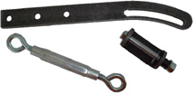 |
|
A typical bracket set |
For more information,
The ZENA mobile welding system is
manufactured in the USA and is sold with a
36
month limited warranty.
You have no risk if you buy on-line or order by phone.
ALL welders sold direct to end users come with a 60-day money back guarantee of satisfaction.
US & Foreign Patents Pending
© Copyright 1998,-2005 by ZENA, Incorporated. All rights reserved.
[an error occurred while processing this directive]